CNC-RP: Rapid Prototyping Using Computer Numerical Controlled Machining

The focus of this project is to develop Computer Numerical Controlled (CNC) machining as a rapid manufacturing process. While CNC machining is highly automated, it is not necessarily a rapid process because it requires a skilled person to determine the type and size of tools, the type of cutting operations, sequence of operations, and often most difficult; a fixture design. In our approach, a complex model is machined with layer-based machining operations from several orientations. Software that we are developing determines where these numerous orientations are, what tools are required for each orientation, and how to automatically generate fixture support structures. The goal is to go directly from a CAD model to loading a piece of stock material and pushing the start button, without the hours of planning by a skilled machinist.
The Machining of Metallic Foams for Rapid Manufacturing


The focus of this project is to develop a new process for the machining of metallic foams, in particular, porous metals used in biomedical implants. If a traditional machining approach is used, the surface of the material smears, causing the surface pores of the foam to close. Evidence of this is shown in the traditionally machined sample shown in Figure 1b versus the uncut TM shown in Figure 1a. In contrast, Figure 1c illustrates the same material cut using the method of this newly developed process. This method has been used in conjunction with CNC-RP in the laboratory to illustrate its capabilities. As shown in Figure 2, a CAD model of a bone fragment (due to traumatic fracture) from a human Tibia was reverse engineered from CT scan data and replicated using CNC machining of Trabecular Metal(TM).
US Provisional Patent Application No: 61/024,945: “A Method for Machining Metallic Foams”, M. Frank, Inventor, Submitted January 31st, 2008
Rapid Machining of Bone Fragments for Orthopedic Trauma Research
This project investigates the use of rapid manufacturing of replacement bone fragments using a Subtractive Rapid Prototyping process called CNC-RP. Bone fragments resulting from traumatic injury can be reverse-engineered from medical imaging such as CT scans and then automatically generated in advanced synthetic biomaterials and other bioactive/biocompatible materials. The research provides evidence that suitable bone geometries can be created using subtractive RP from a variety of materials ranging from Trabecular Metal®, polymers, ceramics, and actual bone allografts. The research could impact the effectiveness of orthopaedic surgery for traumatic bone fracture, as custom prototyped bone fragments should aid in bone growth and improve recovery. This work is a collaborative project with the Orthopaedic Biomechanics Laboratory at The University of Iowa Hospitals and Clinics.
Rapid Pattern Manufacturing (RPM): A Hybrid Method for Rapid Pattern Manufacturing in Metal Casting
The focus of this project is to develop a hybrid system for the rapid manufacturing of patterns for the metal casting industry, focusing on large patterns for military prototypes. The process involves an additive/subtractive approach to pattern making using newly developed process planning algorithms. The goal is to develop a completely automated Rapid Pattern Manufacturing (RPM) system which only requires a CAD model as input, and then runs unattended without the need for a skilled pattern maker or other technician.
Computer Automated Manufacturability Analysis: CNCRP-ANA
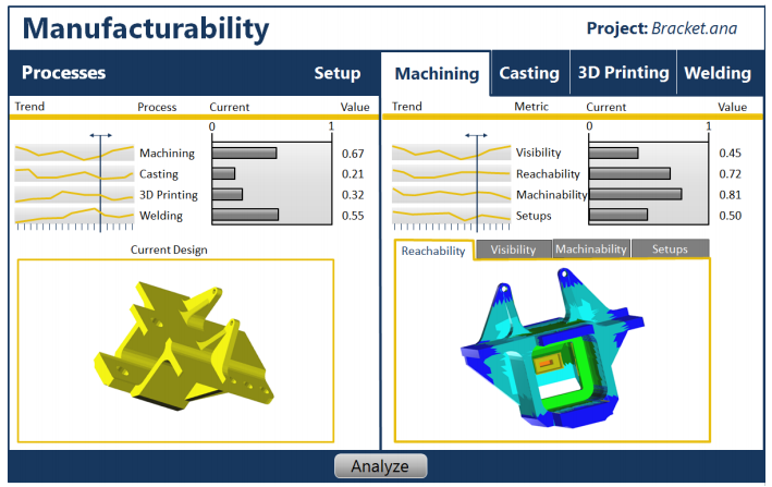
ANA is a software platform for mechanical designers to evaluate conceptual designs for manufacturability. The goal is to provide designers with general feedback regarding how easily their part could be manufactured with casting, die casting, machining, and welding. This will allow designers to reevaluate and modify design decisions which have significant negative effects on manufacturability. By correcting designs, more manufacturing methods should be available when it comes time for production or moving from low to high volume production.
Rapid Tooling Using Friction Stir Welding and Machining
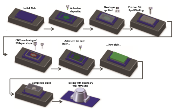
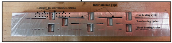
This project investigates a friction stir molding (FSM) method for the rapid manufacturing of metal tooling. The method uses additive and subtractive techniques to sequentially friction stir bond and then mill slabs of metal. Mold tooling is grown in a bottom-up fashion, overcoming machining accessibility problems typically associated with deep cavity tooling. To test the feasibility of FSM in building functional molds, a layer addition procedure that combines friction stir spot welding (FSSW) with an initial glue application and clamping for slabs of AA6061-T651 was investigated. Additionally, FSSW parameters and the mechanical behavior of test mold materials, including shear strength and hardness, were studied. Further, scanning electron microscopy (SEM) /elemental map analysis (EDS) of the spot weld zones was carried out to understand the effect of FSSW on the glue materials and to study potential mixing of glue with the plate materials in the welded zone. The results indicate that FSM provides good layer stacking without gaps when slabs are pre-processed through sand blasting, moistening, uniform clamping, and friction stir spot welding using a tapered pin tool. The tensile shear strength results revealed that the welded spots were able to withstand cutting forces during machining stages; however, FSSW was found to cause hardness reduction among spot zones because of over-aging. The SEM/EDS results showed that glue was not mixed with slab materials in spot zones. The proposed process was able to build a test tooling sample successfully using AA6061-T651 plates welded and machined on a 3-axis CNC mill.
Hybrid Manufacturing: Combining Additive and Subtractive Techniques
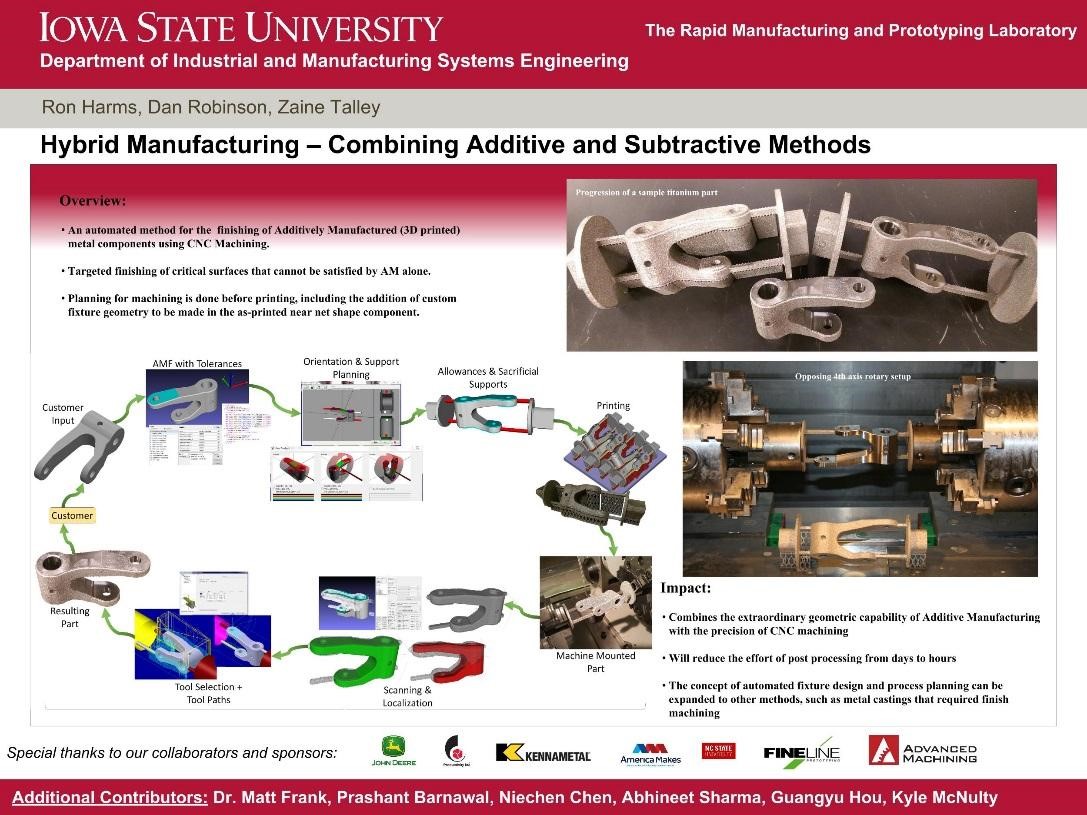
The project involving hybrid manufacturing (CNC-RP Hybrid) is aimed at creating a manufacturing process which increases the desirability of metal 3D printing. Here we can combine the positive qualities of metal 3D printing with the dimensional accuracy of conventional machining. This process, which is illustrated as a circular flow chart in the image above, is a complete progression from digital CAD model through the final manufactured part.
First, a cad model of the desired part to be manufactured is created and then loaded into “AMF Creator”. Here critical features are labeled as the designer desires. These flats, holes, and free forms will be post machined in order to achieve near perfect dimensional accuracy as well as very fine surface finishes. The model next has supports added, in order to hold the printed part in the 4th axis setup within the VMC. Now the model is ready for printing. After printing, the parts are separated from the build tray, and fixture into the VMC. Here the part is 3D scanned, in order to create a stock model for tool path generation. Lastly, toolpaths are generated using automated CNCRP software.